Engineering mechanics (EM) short notes GATE
Posted by Sajid Khan | Last updated on
This page is split into multiple parts.
- Engineering mechanics (EM) short notes GATE | Part-1
- Engineering mechanics (EM) short notes GATE | Part-2
Note: Incomplete
Syllabus: Free-body diagrams and equilibrium; trusses and frames; virtual work; kinematics and dynamics of particles and of rigid bodies in plane motion; impulse and momentum (linear and angular) and energy formulations, collisions.
Engineering Mechanics basics and important formulas
Engineering mechanics deals with the effect of forces on bodies. EM has three parts:
- Statistics: Deals with forces acting on a body.
- Example: Analysis of truss
- Kinematics: Studies only the motion of the bodies.
- Example: Projectile motion
- Kinetics: Deals with the motion as well as different forces acting on the bodies.
- Example: Collision
Newton’s laws of motion:
- First law: Body remains in it’s state of rest or motion (inertia)
- Second law: Force, \(F\) = Rate of change of linear momentum (\(mv\)) with respect to time
or \(F = ma\) \[ F = \frac{ (mv_2 – mv_1) }{ t }\] \[\ =\ m\frac{ (v_2 – v_1) }{ t }\] \[\ =\ ma \] - Third law: To every action, there’s always an equal and opposite reaction.
- Body remains in it’s state of rest or rotational motion
- Torque, \(T\) = Rate of change of angular momentum with respect to time
or \[ T = \frac{mv_2r – mv_1r}{t} = mr\left(\frac{v_2 – v_1}{t}\right)\ =\ mra\ =\ mr^2\alpha\ \ =\ I\alpha \]
or \(T = I\alpha\)
Mass, Force, Work done, Power, and Energy
- Mass:Mass is the indication of quantity of material.
- Mass is a scalar quantity
- usually denoted by a small letter \( m \)
- SI unit of mass is Kilogram, or Kg
- Force: An external agent or an intersection, that tends to change or maintain the motion of an object
- Force is a vector quantity
- Usually denoted by capital letter \( F \)
- \( F=ma \)
- SI unit of force is Newton, or N
\[ N=\text{Kg}\frac{m}{s^2} \] - Gravitational metric unit of force is Kilogram-force or Kgf
- 1 Kgf = 9.8 N
- 1 Kgf = 9.8 N
- Weight: Weight of any body, is the force exerted by that body due to local gravity.
- A body of mass \(m\) has weight, \( w=mg \) ( g is acceleration due to gravity )
- 1 Kg mass experiences 9.8 N or 1 Kgf of force due to gravity.
- Work done:Work is done when the an object is displaced from it’s original position due to an applied force.
- Work done is a scalar quantity
- Usually denoted by capital letter \(W\)
- Work done is the dot product of Force and displacement vector. Assuming a force F of constant magnitude, work done is calculated as:
- \( W=Fd\cos\theta \) \(F\) and \(d\) are the magnitude of Force and Displacement vectors, both force and displacement vectors are separated by an angle \(\theta\)
- When the angle between force and displacement vectors is zero (ie. body is moved only in the direction of applied force), then
\( W=Fd \)
- Graphically, Work done is the area under the curve drawn by the force with respect to distance
- When the applied force is constant with respect to the movement of the body, then
Work done, \( W=Fx \) \(x\) is the distance moved by body in the direction of applied force,
or in other words, It is the displacement of body in the direction of applied force
If \(d\) is the actual displacement of body then, \( x=d\cos\theta \) - When the applied force is not constant (ie. when force is a function of \(x\)) ( example: spring force, force applied by a person to push a body ), then
Work done, \[ W=\int Fdx \] - When the force and \(x\) has a linear relation (ie. when \( F\propto x \)) ( example: spring force, force applied by a UTM machine ), then
Work done, \[ W=\frac{1}{2}Fx \]
- When the applied force is constant with respect to the movement of the body, then
- SI Unit of work done is Jule, or J
\[ J=Nm=Kg\frac{m^2}{s^2} \] - #todo attach different workdone curves here
- Power :Power is the amount of work done with respect to time
- Power is a scalar quantity
- Usually denoted by capital letter \(P\)
- \[ P=\frac{\text{Work done}}{\text{time}} \]
- SI Unit of Power is Watt, or W
- \[ \text{W}=\frac{J}{s} \]
- “Watt hour”, or Wh is another unit of Power. It is equivalent to the amount of work done in one hour.
\[ \text{Wh}\ =\ \frac{\text{Jule}}{\text{Hour}}\ =\ 3600\ \frac{J}{s}\ =3600\text{ Watt} \]
- Energy: Energy of a system indicates the amount of work that can be done by the system.
- More the energy \( \implies \) More work can be done.
- Since it measures the amount of work done,
- Energy is a scalar quantity.
- SI unit of energy is also Jule, or J
- Other unit of energy includes “Watt hour”, or Wh. It is equivalent to the amount of work that can be done in one hour.
\[ \text{Wh}\ =\ \frac{\text{Jule}}{\text{Hour}}\ =\ 3600\ \frac{J}{s}\ =3600\text{ Watt} \]
- A system of mass m, moving with velocity \(v\) stores the kinetic energy,
- \[ K.E.\ =\frac{1}{2}mv^2 \]
- A system of mass \(m\) kept at height \(h\) above the ground, it can do work by falling. The energy stored by this system is potential energy,
- \( P.E.=mgh \) ( \(g\) is the acceleration due to gravity)
Moment of force (Torque)
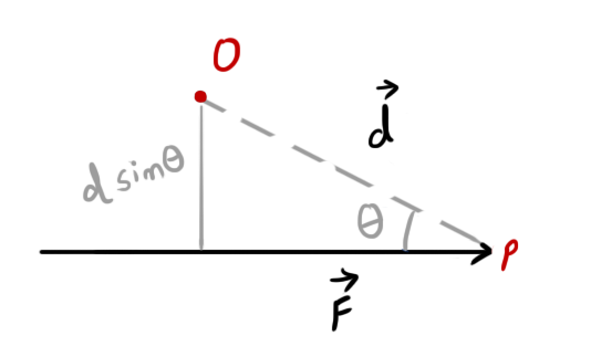
Moment of a force \(F\) about a point O when the force is applied on a point P is given by:
\( \vec{M}=F\ d\sin\theta\ \hat n \)
- Moment of force (Torque) is a vector quantity.
- Magnitude of moment of force is:
- \( M=Fd\sin\theta \)
- From the diagram, it is clear that:
Magnitude of moment of force = Force \(\times\) perpendicular distance of point O from the line of action of force - Moment of force is always taken with reference to a point (that may or may not lie on the line of action of force).
- Moment of force is also refereed to as Torque.
Varignon’s theorem (Principle of moments)
Varignon’s theorem states that the Moment of Resultant of two forces is equal to the algebraic sum of moment of individual forces.
Law of moments
When a body is in equilibrium, the sum of all clockwise moments on the body is equal to the sum of all anti-clockwise moments.
\( \Rightarrow \) For an equilibrium system, \[ \sum_{ }^{ }M=0 \]
Couple
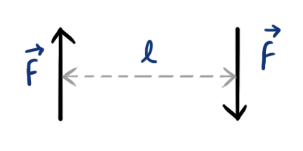
Two equal, parallel, and opposite forces, separated together by a finite distance form a couple.
The distance between two opposite forces is called the Arm of Couple.
- Moment of forces forming a couple is given as
- \[ M=Fl \] ( \(l\) is the arm of couple)
- The Moment of forces forming a couple remains same at every point that lies on the plane of couple.
- A couple can not be balanced by single force, It can be balanced only by another couple of opposite direction and equal moment of force.
Linear-Rotational Parallels
| Sr.no. | Linear Motion | Rotational Motion ( radius = r ) |
| 1 | Displacement, \(d\) | Angular displacement, \(\theta\) \( \theta=d/r \) |
| 2 | Velocity, \(v\) \[ v=d/t \] | Angular velocity, \( \omega \) \[ w=\theta /t \] \[ w=v/r \] |
| 3 | Acceleration, \(a\) \[ a = v/t \] | Angular acceleration, \(\alpha\) \[\alpha = w/t\] \[\alpha = a/r\] |
| 4 | Mass, \(m\) | moment of Inertia, \(I\) \[I=mr^2\] |
| 5 | Force, \(F\) \[F = ma\] | Torque (moment of Force), \(T\) or \( \tau \) \[\tau = I\alpha\] \[\tau = Fr\] |
| 6 | Work, \(W\) \[ W=Fd \] | Work, \(W\) \[W=\tau\theta\] |
| 7 | Power, \(P\) \[P=Fv\] | Power, P \[P=\tau \omega\] |
| 8 | Energy \[ K.E.=\frac{1}{2}mv^2 \] | Energy \[ K.E.=\frac{1}{2}I\omega^2 \] |
Vectors
Read explanation for Vectors here.
Vector basics
- If \(\vec{V}\) or \( \textbf{V} \) denotes a vector, then
- It’s magnitude is denoted by \( \left|\vec{V}\right| \) or \( \left|\textbf{V}\right| \) or \(V\)
- A unit vector having the direction parallel to \(\vec{V}\) is denoted by \(\hat{v}\)
- Unit vector parallel to a vector \(\vec{V}\) is given by, \[ \hat{v}=\vec{\frac{V}{\left|\vec{V}\right|}}=\vec{\frac{V}{V}} \]
- Angle made by \[ \vec{V}=xi+yj \] with X axis, \[ \theta=\tan^{-1}\left[\frac{y}{x}\right] \]
- or, if Angle \(\theta\) is known, components can be calculated as,
\(x = V\cos\theta \)
\(y = V\sin\theta \)
- or, if Angle \(\theta\) is known, components can be calculated as,
- Magnitude of vector \[ \vec{V}=xi+yj \] is given by, \[ V=\sqrt{x^2+y^2} \]
Parallelogram law of vectors
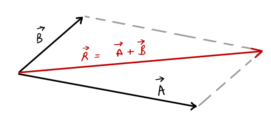
If \( \vec{A}\text{ and }\vec{B} \) are two vectors parallel-shifted to denote two sides of a parallelogram,
then resultant, \( \vec{R}=\vec{A}+\vec{B} \)
Triangle law of vectors
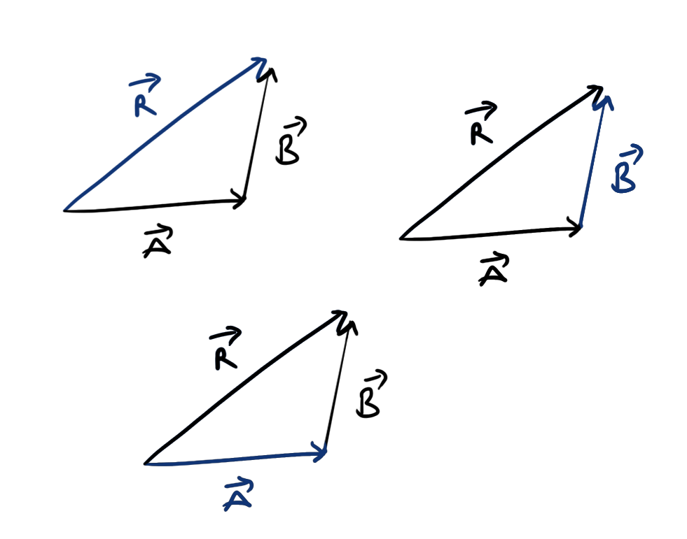
For a system of 3 vectors as shown in figure,
\[ \begin{aligned} &\vec{R}=\vec{A}+\vec{B}\\ \text{or}\ \ & \vec{A}=\vec{R}-\vec{B}\\ \text{or}\ \ &\vec{B}=\vec{R}-\vec{A} \end{aligned} \]
Resultant and resolution of vectors
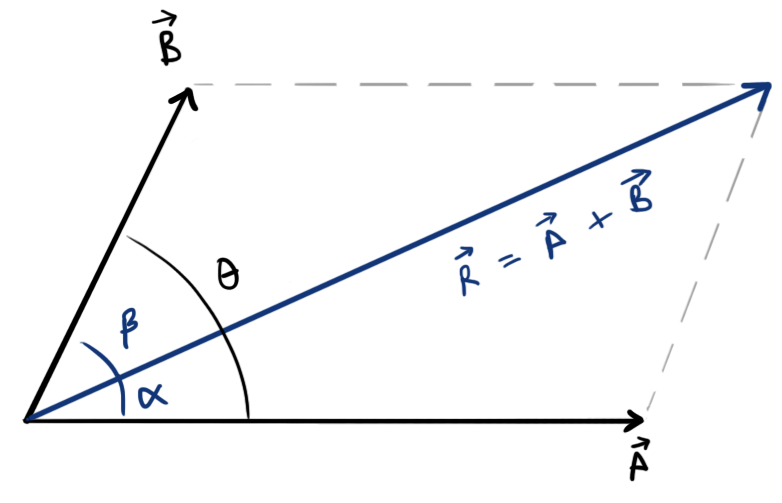
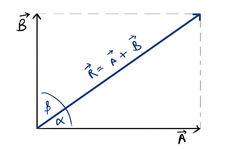
- Resultant of two vectors \(\vec{A}\) and \(\vec{B}\) separated by angle \(\theta\)
- Magnitude, \( R=\sqrt{A^2+B^2+2AB\cos\theta} \)
- Angle made from \(\vec{A}\), \[ \alpha=\tan^{-1}\left[\frac{B\sin\theta}{A+B\cos\theta}\right] \]
- Resultant of two orthogonal vectors \(\vec{A}\) and \(\vec{B}\)
- Magnitude, \( R=\sqrt{A^2+B^2} \)
- Angle made from \(\vec{A}\), \[ \alpha=\tan^{-1}\left[\frac{B}{A}\right] \]
- Resolution of a vector \(\vec{R}\) along two vectors \(\vec{A}\) and \(\vec{B}\) separated from \(\vec{R}\) by angle \(\alpha\) and \(\beta\) respectively is given by:
- Magnitude, \[ A=R\frac{\sin\beta}{\sin\left(\alpha+\beta\right)} \]
- Magnitude, \[ B=R\frac{\sin\alpha}{\sin\left(\alpha+\beta\right)} \]
- Resolution of a vector \(\vec{R}\) along two orthogonal vectors \(\vec{A}\) and \(\vec{B}\) separated from \(\vec{R}\) by angle \(\alpha\) and \[ 90^{\circ}-\alpha \] receptively is given by:
- Magnitude, \( A=R\cos\alpha \)
- Magnitude, \( B=R\sin\alpha \)
Vector product
If \(vec{A}\) and \(\vec{B}\) are two vectors, then
- Dot product: It is the product of magnitude of \(\vec{A}\) and magnitude of projection of \(\vec{B}\) onto \(\vec{A}\)
- \( \vec{A}\cdot\vec{B}=AB\cos\theta \)
- Dot product of two vectors results in a scalar quantity
- Work done is an example of dot product of force and displacement vector.
- \( W=fd\cos\theta \)
- Cross product: Cross product of two vectors results in a vector quantity whose magnitude is equal to the area of the parallelogram formed by two vectors, and direction is perpendicular to the plane containing the two vectors.
- \( \vec{A}\times\vec{B}=AB\sin\theta\ \ \hat{n} \)
- Torque is an example of cross product of force and position vector of point on which force is applied
- \( \vec{T}=Fr\sin\theta\ \ \hat{n} \) \(r\) is the position vector of point on which force was applied
\(\theta\) is the angle between \(F\) and \(r\)
\(\hat{n}\) is a unit vector perpendicular to both \(F\) and \(r\) - or, \( T=Fr\sin\theta\ \)
- \( \vec{T}=Fr\sin\theta\ \ \hat{n} \) \(r\) is the position vector of point on which force was applied
- The direction of \(\hat{n}\) is determined by using the Right hand rule.
Force system
Group of two or more forces acting on a single system/object is called a force system ( or system of force ).
Types of force system
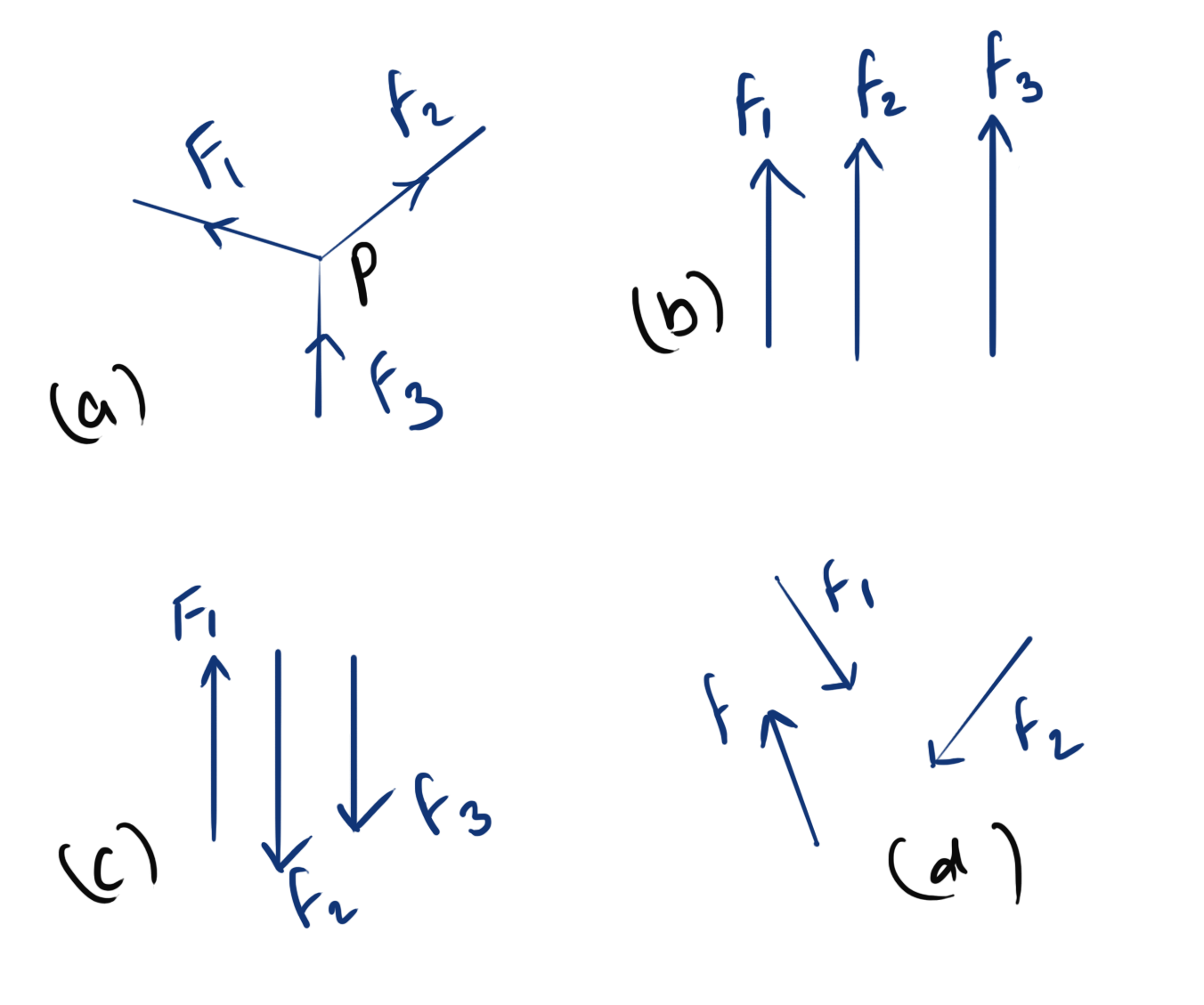
- Co-planer forces: All forces lie in a single plane
- concurrent forces: All forces pass through a common point
- parallel forces: All forces are parallel to each other
- like forces: Parallel forces acting in same direction
- unlike forces: Parallel forces acting in opposite direction
- Non-cuncurrent non-parrallel forces
- Non co-planer forces: System of non co-planer forces is system of two or more forces that lie in more than one plane.
Types of non co-planer forces are analogous to that of co-planer forces
Resultant and resolution of Concurrent Forces
- Resultant of two forces \( F_1 \) and \(F_2\) separated by angle \(\theta\)
- resultant, \( R=\sqrt{F_1^2+F_2^2+2F_1F_2\cos\theta} \)
- angle of resultant \(R\) made with force \(F_1\), \[ \alpha=\tan^{-1}\left[\frac{F_2\sin\theta}{F_1+F_2\cos\theta}\right] \]
- Resultant of two orthogonal forces \(F_1\) and \(F_2\)
- resultant, \( R=\sqrt{F_1^2+F_2^2} \)
- angle made with \(F_1\), \[ \alpha=\tan^{-1}\left[\frac{F_2}{F_1}\right] \]
- Resolution of a force \(F\) into two forces \(F_1\) and \(F_2\) separated by angles \(\alpha\) and \(\beta\) respectively
- \[ F_1=F\frac{\sin\beta}{\sin\left(\alpha+\beta\ \right)} \]
- \[ F_2=F\frac{\sin\alpha}{\sin\left(\alpha+\beta\ \right)} \]
- Resolution of a force into two orthogonal forces \(F_1\) and \(F_2\) separated by angles \(\alpha\) and \(\beta\) ( \( =\alpha+90^{\circ} \) ) respectively
- \( F_1\ =\ F\cos\alpha\ =\ F\sin\beta \)
- \( F_2\ =\ F\cos\beta\ =\ F\sin\alpha \)
Theorem of Resolution (Theorem of resolved parts)
The algebraic sum of resolved parts of two vectors in any given direction equals to the resolved part of the resultant vector in the same direction.
Principle of Transmissibility
States that, If the Force on a system is translated along its line of action (keeping the direction unchanged), then the system remains unchanged & unaffected.
#todo diagram
Resultant of Parallel forces
- The resultant of two or more parallel forces is also parallel to those forces.
- The magnitude of Resultant of parallel forces is algebraic sum of magnitude of each force.
=> \[ R=\sum F_i \]
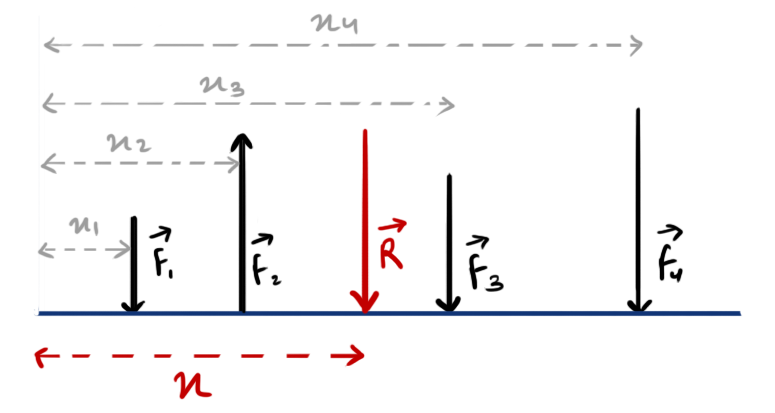
- The position of Resultant of parallel forces is obtained with the help of Varignon’s theorem by equating Moment of Resultant force and algebraic sum of moment of each force.
- \[ Rx=\sum_{i=1}^nF_ix_i \]
- \[ x=\frac{\sum F_ix_i}{\sum F_i} \]
- \[ Rx=\sum_{i=1}^nF_ix_i \]
Hence, For the system of parallel point forces as shown in above figure,
resultant \( R=F_1-F_2+F_3+F_4 \)
and, \( Rx=F_1x_1-F_2x_2+F_3x_3+F_4x_4 \) or,
\[ x=\frac{F_1x_1-F_2x_2+F_3x_3+F_4x_4}{R} \]
Polygon law of forces (or vectors)
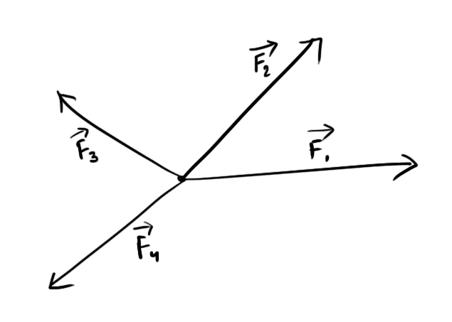
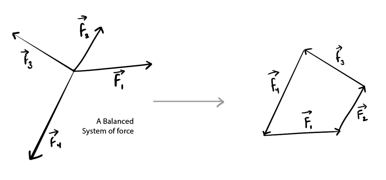
Polygon law states that, If all the forces of a system can be represented by the sides of a polygon taken in same order with same angle/direction, Then the resultant of those forces can be represented by the closing side of that polygon taken in opposite order.
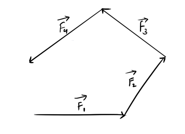

If the Polygon formed by the forces is a closed polygon, then the Resultant of the forces is Zero
Sine rule
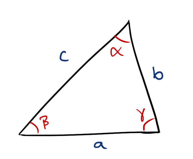
For any closed triangle with sides a, b, and c, having the angles \( \alpha,\ \beta,\) and \(\gamma\) opposite to the sides respectively,
\[ \frac{a}{\sin\alpha}=\frac{b}{\sin\beta}=\frac{c}{\sin\gamma} \]
or \[ \frac{\sin\alpha}{a}=\frac{\sin\beta}{b}=\frac{\sin\gamma}{c} \]
Lami’s theorem
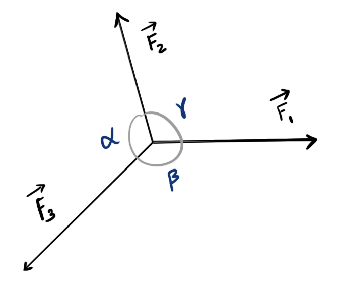
Lami’s theorem states that, if the system of three concurrent forces is in equilibrium, then each force is proportional to the sin of angle made by other two forces
For the equilibrium system shown in figure,
\[ \frac{F_1}{\sin\alpha}=\frac{F_2}{\sin\beta}=\frac{F_3}{\sin\gamma} \]
Lami’s theorem can be proved by applying polygon law and sin rule
Next Part
This page is split into multiple parts.
- Engineering mechanics (EM) short notes GATE | Part-1
- Engineering mechanics (EM) short notes GATE | Part-2
