Engineering mechanics (EM) short notes GATE
Posted by Sajid Khan | Last updated on
This page is split into multiple parts.
- Engineering mechanics (EM) short notes GATE | Part-1
- Engineering mechanics (EM) short notes GATE | Part-2
Mechanical Equilibrium
A system is in mechanical equilibrium when the sum of all the forces and moment of forces acting upon the system is zero.
\( \Rightarrow \) In an equilibrium system, \[ \sum_{ }^{ }F=\sum_{ }^{ }M=0 \]
Types of mechanical equilibrium
- Static Equilibrium: When a system is at rest and is in mechanically equilibrium, the system is said to be in static equilibrium.
- A statically equilibrium system will always be at rest. It will start moving only when an external force is applied. By applying an external force, the system will no longer be in mechanical equilibrium.
- Dynamic Equilibrium: If a system is in motion with a constant velocity and if the sum of all the forces acting upon it is zero, then the system is said to be in dynamic equilibrium.
- A dynamically equilibrium system will keep moving with the constant velocity forever. The motion of such system can be changed by applying an external force i.e. by braking the conditions of equilibrium.
Free body diagrams (FBD)

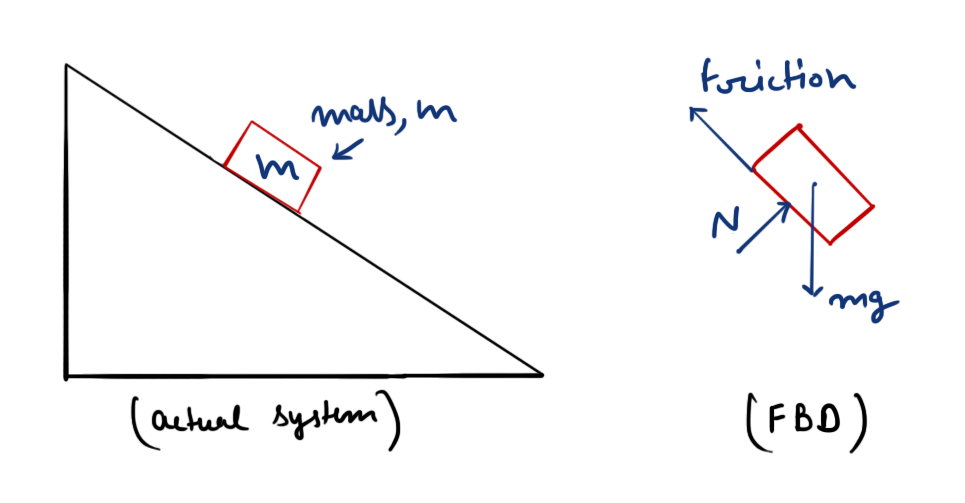
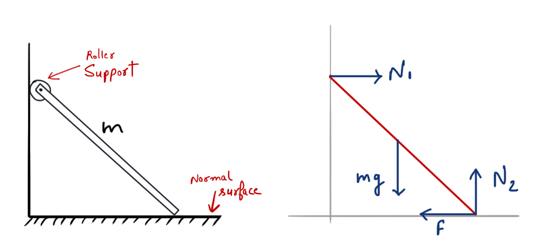
A free body diagram of a system is the symbolic representation of system with the help of all the forces (including reaction forces) acting on it. The various types of forces included (but not limited to) in FBD’s are Reaction force, Friction force, Gravitational force, and Applied force
Points to remember when drawing Free body diagrams
- Free body diagram must depict all the forces acting on the system.
- For normal contact surfaces (or at Hinged joints), Friction force along with normal force is also considered when drawing FBD’s. Both Friction force and Normal force add up to make the resultant reaction force that may or may not be normal to the contact surface.
- For smooth contact surfaces (or at roller supports), Friction force doesn’t exist, hence only Normal force is considered. The reaction force at smooth contact surfaces is equal to the normal force, always perpendicular to the surface at point of contact.

More Free body diagram examples
#todo attach example images here.
Trusses and frames
- Truss is a group of beams (called members) assembled together to create a rigid structure.
#todo diagram of a simple truss. mark members and joints with arrows
Classification of truss
- Planar truss: All the members and joints of truss lie in a single plane.
- Space truss: Members and Joints of such truss lie in 3 dimensions.
- Perfect truss: A truss is said to be perfect when the number of members and joints of the truss has the following relation:
- \( m=2j-3 \)
- Here \(m\) is number of members in the truss, and \(j\) is the number of joints in the truss.
- #todo diagram of perfect truss
- A perfect truss is Rigid in nature, no deformation occurs when load is applied on such trusses.
- Deficient truss: The number of members and joins of deficient truss hast the following relation:
- \( m<2j-3 \)
- #todo diagram of deficient truss
- Deficient trusses are not rigid in nature, any kind of load applied causes deformation in such truss.
- Redundant truss: The number of members and joints of redundant truss has the following relation:
- \( m>2j-3 \)
- #todo diagram of redundant truss
- Redundant trusses are also rigid in nature.
- Statistically determinant trusses:
- Statistically in-determinant trusses:
Next Part
This page is split into multiple parts.
- Engineering mechanics (EM) short notes GATE | Part-1
- Engineering mechanics (EM) short notes GATE | Part-2
